2026 Top Bed of Nails Test Fixture Buying Guide

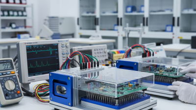
Choosing the right bed of nails test fixture can determine whether a 2026 production line runs smoothly or quietly creates false failures. This guide examines fixture accuracy, probe quality, mechanical durability, signal integrity, and long-term maintenance. It also considers board size, test-point density, connector access, and operator safety. Small details matter. A worn probe can leave a bright mark and an unreliable result.

John McLinn, a veteran test-fixture engineer, offers a practical reminder: “Reliable contact begins with controlled mechanics, not software.” His point remains relevant for modern ICT and functional testing. Advanced software cannot compensate for uneven compression, poor support tooling, or incorrectly selected probes. Buyers should inspect repeatability data, compression limits, fixture materials, and service procedures before approving a supplier. Ask for sample results, not impressive claims.

The best bed of nails test fixture is not always the most expensive model. It must fit the product, process, and expected production volume. A low-volume prototype may need flexibility, while an automotive assembly line may require rugged construction and rapid changeover. There is no universal winner. Even experienced teams sometimes underestimate setup time, cable routing, or replacement-part costs. That deserves reflection.

This 2026 buying guide helps engineers compare suppliers with clearer criteria. It covers pneumatic and manual designs, custom probes, vacuum-assisted systems, modular tooling, and automated test integration. Readers will also find practical questions for factory trials and acceptance testing. The goal is straightforward: achieve stable contact, repeatable measurements, and fewer unnecessary retests. Good fixtures do not merely hold circuit boards. They protect production confidence.

2026 Top Bed of Nails Test Fixture Buying Guide

What Is a Bed of Nails Test Fixture and How Does It Work?

What Is a Bed of Nails Test Fixture and How Does It Work?

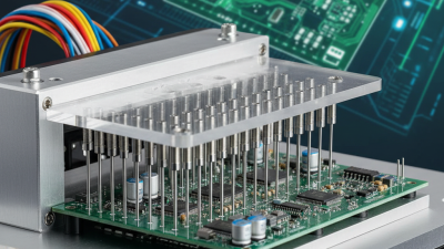
A bed of nails test fixture checks a populated circuit board through many spring-loaded probes. Each probe touches a designed test pad, via, or connector contact. The fixture presses the board downward with mechanical, pneumatic, or vacuum force. A test system then measures continuity, resistance, shorts, and selected functional signals. Some setups also support programming and insulation checks. It is fast because many points are tested in parallel. Grand View Research’s 2024 automated test equipment report valued the wider market at approximately US$7 billion in 2023. It also forecasts growth of about 8% annually through 2030. That growth reflects demand for repeatable electronics inspection.

Tips: Confirm test-pad access before designing the fixture. Keep probe travel within the supplier’s rated range. Use replaceable probes, since contamination and wear can create false failures. IPC-9252 guidance emphasizes controlled electrical testing and reliable measurement methods. In practice, fixture alignment matters as much as software settings. A slightly warped board can produce uneven contact pressure. That detail is easy to miss.

A bed of nails is not universal. It needs stable reference points and suitable test access. Dense boards may require smaller probes and tighter tooling tolerances. High-volume production benefits from short test cycles, but prototypes may need flexible probing. I have seen teams blame software when worn probes caused intermittent readings. That assumption deserves review. Record probe resistance, contact force, and failure locations during maintenance. These simple records improve traceability and prevent repeated guesswork.

Key Fixture Types and Their Suitable Testing Applications

2026 Top Bed of Nails Test Fixture Buying Guide

Key Fixture Types and Their Suitable Testing Applications

A bed of nails fixture connects a printed circuit board to test equipment through spring-loaded probes. The right fixture depends on production volume, board design, and required test depth. Universal fixtures suit prototypes and low-volume production because their probe layouts can be adjusted. They reduce setup time, but contact consistency may require careful inspection.

Dedicated fixtures are built for one board family and repeated testing. They offer stable positioning, faster loading, and reliable electrical contact in high-volume manufacturing. Pneumatic fixtures can apply controlled pressure across larger boards. They work well for in-circuit testing, continuity checks, resistance measurements, and selected functional tests. Vacuum fixtures can support slim assemblies, although sealing problems may affect repeatability.

Tips: Check probe travel, board support, connector clearance, and operator access before ordering. Ask for calibration records and a sample contact-resistance report. Replace worn probes early. Small wear can create confusing failures. Fixture wiring also matters when testing high-speed signals; poor routing may introduce noise. No fixture is perfect. A design that works well in a laboratory may struggle beside a busy production line. I have found that simple loading mechanisms often outperform complex designs when operators repeat the same motion hundreds of times daily. Leave room for future test points, even when the current board seems stable.

How to Match Probe Layouts with PCB Design Requirements

A bed of nails test fixture should follow the PCB, not force the PCB into a convenient grid. Start with the schematic’s test strategy. Mark power rails, ground points, boundary-scan nodes, analog nets, and high-risk interfaces. Then compare those locations with available test pads. IPC-2221B guidance supports practical spacing and manufacturability checks, but it cannot replace a real probe-access review.

Probe pitch matters. A 2.54 mm grid suits larger through-hole pads, while dense boards may need 1.27 mm or finer layouts. Keep probes away from tall capacitors, connectors, heat sinks, and uneven solder joints. The fixture must also support the board near every high-force probing region. Otherwise, a thin PCB can flex, creating intermittent contact. I have seen clean electrical designs fail because support pins were placed too late.

Industry pressure makes this detail less forgiving. IPC’s 2024 Electronics Industry Sentiment Survey identifies cost and supply-chain pressure as continuing manufacturing concerns. A poorly matched fixture increases retesting and operator time. The Global E-waste Monitor 2024 reports 62 million tonnes of electronic waste generated in 2022, making avoidable scrap harder to ignore. Select probe tips for the surface finish, keep the signal path short, and verify the fixture’s compression force. I would not trust a layout based only on CAD spacing. Real components vary, and my first fixture assumptions are often too optimistic. Test a populated sample before approving production tooling.

Essential Factors for Evaluating Fixture Quality and Compatibility

A bed of nails fixture should be judged by contact reliability, not appearance. During production trials, inspect probe marks, board support, clamping pressure, and cable routing. A stable fixture keeps every probe aligned after repeated loading. It should also prevent panel flex near large connectors and transformers. Small details matter.

Compatibility begins with the PCB, not the fixture frame. Check board thickness, hole locations, component heights, test-pad spacing, and access from both sides. The fixture must match the tester’s voltage, current, signal frequency, and interface wiring. IPC-2221 guidance on printed-board design supports careful spacing and mechanical review before tooling. The 2024 Automated Test Equipment Market report from MarketsandMarkets estimated continued market growth through 2029. That trend reflects rising demand for faster, repeatable electrical inspection.

Measure quality with evidence. Record contact resistance across repeated cycles, false-fail rates, setup time, and fixture wear. A practical acceptance test should include at least 100 loading cycles, with results logged by operator and board type. Keep the data. It exposes weak springs and unstable support points. My own fixture reviews often find that a lower-cost design performs well initially, then drifts after several weeks. This is easy to miss. One limitation remains: published market reports rarely measure fixture durability directly. Buyer trials must fill that gap. Request drawings, maintenance instructions, replacement-part data, and a clear compatibility matrix before approval.

2026 Top Bed of Nails Test Fixture Buying Guide

Essential Factors for Evaluating Fixture Quality and Compatibility

The chart shows a practical evaluation weighting for selecting a bed of nails test fixture. Contact reliability and DUT compatibility receive the highest emphasis because probe alignment, pad access, board support, and stable electrical contact directly affect test repeatability. Mechanical durability, signal integrity, operator safety, and serviceability should also be verified before purchase.

How to Select, Install, Maintain, and Replace a Test Fixture

2026 Top Bed of Nails Test Fixture Buying Guide

Selecting a bed of nails test fixture starts with the circuit board, not the fixture frame. Check board thickness, connector locations, test points, and expected production volume. A reliable fixture should apply even pressure without bending the board. Spring probes must match pad size, spacing, and test current. Leave clearance around tall components. I once underestimated a heat sink’s height, causing uneven contact during testing.

Installation should be measured, not rushed. Secure the fixture on a stable, level surface. Verify probe alignment with a sample board before applying full pressure. A gentle first closure can reveal interference or movement. Inspect wiring, grounding, and signal paths with a calibrated meter. Keep test records, including failed points and probe replacements. My early checklist was too optimistic; repeated checks found small alignment errors.

Tips: Clean probe tips regularly, and replace damaged springs immediately. Do not force the lid closed. During maintenance, inspect worn guides, loose screws, cracked supports, and compressed probes. Replace the fixture when repeatability declines, repairs become frequent, or the board design changes significantly. Store it covered and dry. Label every cable clearly. Small details matter.

2026 Top Bed of Nails Test Fixture Buying Guide - How to Select, Install, Maintain, and Replace a Test Fixture
Stage Data Dimension Practical Specification or Guideline Typical Value, Limit, or Trigger Acceptance Check
Select Test coverage Define whether the fixture will support in-circuit test, power-on functional test, boundary-scan access, programming, or a combined sequence. List every required test node, connector, probe, power input, signal interface, and mechanical access point before design approval. Every required test point has a documented electrical or mechanical access method.
Select PCB size and outline Specify the maximum board length, width, thickness, edge clearance, tooling-hole location, and component keep-out zones. Use the actual production PCB drawing plus manufacturing tolerance; do not size the fixture from nominal dimensions alone. The board seats without interference, bending, or contact with restricted components.
Select Probe pitch Choose probe spacing according to test-pad density and the smallest required pad-to-pad clearance. Common grid pitches include 2.54 mm and 1.27 mm; finer pitches require tighter alignment and greater maintenance control. Probe tips remain centered on test pads across the complete PCB tolerance range.
Select Probe type Match the tip style and stroke to the pad finish, pad size, current level, contamination risk, and expected cycle count. Use pointed or crown tips for many solderable test pads; use suitable high-current or coaxial probes for specialized circuits. Contact resistance and mechanical travel meet the test-system limits under repeated cycling.
Select Probe travel and force Provide sufficient overtravel to compensate for board variation while avoiding excessive PCB deflection and pad damage. A common spring-probe design uses approximately 1.0–2.0 mm of working travel; verify the specific probe datasheet. All probes achieve reliable contact without bottoming out or permanently deforming the PCB.
Select Total clamping load Calculate the combined force of all active probes and confirm that the PCB support structure can distribute the load. Use the probe manufacturer’s specified working force; add a safety margin for uneven loading and fixture wear. Board deflection remains within the engineering limit during a fully compressed test cycle.
Select Board support Use adjustable support posts, support pins, or dedicated tooling features beneath areas exposed to high probe density or heavy components. Place supports near concentrated probe fields and avoid unsupported spans that can flex during compression. No visible PCB bowing, cracked solder joints, or intermittent contact occurs during actuation.
Select Tooling and alignment Use tooling holes, edge guides, datum pins, or equivalent repeatable registration features. Use at least two non-collinear datum references when the PCB design permits them. Board placement repeatability is adequate for the smallest test pad and connector tolerance.
Select Electrical isolation Separate adjacent nets, high-voltage areas, shield connections, and grounded mechanical elements where required. Maintain the applicable clearance and creepage distances for the circuit voltage and pollution environment. Insulation resistance, dielectric withstand, and continuity tests pass the approved limits.
Select Safety and interlock Include a guarded operating area, lid or actuator interlock, emergency-stop integration, and safe discharge provisions where applicable. The tester must not start when the fixture is open, mispositioned, or not fully clamped. Opening or misaligning the fixture removes the test-enable signal and leaves hazardous outputs in a safe state.
Select Pneumatic or manual actuation Choose actuation based on cycle rate, operator ergonomics, available utilities, and required compression consistency. Manual fixtures suit lower-volume work; pneumatic actuation is generally better for repeatable, higher-cycle operation. Compression force and cycle time remain stable throughout the intended operating range.
Install Fixture mounting Mount the fixture on a rigid, level surface and protect cables from pinch points, sharp edges, and repeated bending. Confirm mounting-hole alignment, connector reach, grounding, and operator access before final tightening. The fixture does not shift, rock, or transfer excessive force to external connectors during operation.
Install Probe installation Insert probes to the specified height and orientation. Do not force probes into misaligned guide plates. Replace bent, contaminated, damaged, or inconsistent probes before commissioning. Each probe moves freely, returns correctly, and shows no abnormal friction or sticking.
Install Wiring and signal integrity Route power, ground, analog, digital, and high-speed signal wiring according to the tester design and noise-control requirements. Keep sensitive signal paths short where practical and provide strain relief at moving interfaces. Continuity, polarity, shielding, grounding, and required signal-quality measurements pass the test plan.
Install Initial calibration Verify probe contact, fixture identification, test-program mapping, and any force, position, or voltage measurement channels. Perform calibration after assembly, after major repair, and whenever a critical alignment component is replaced. Calibration records are traceable to the fixture serial or internal asset identifier and date.
Install First-article validation Run known-good and known-fault samples before releasing the fixture for production. Use multiple boards when possible to confirm repeatability across normal PCB variation. Good units pass consistently and deliberate fault samples are detected as intended.
Maintain Daily visual inspection Check the fixture surface, lid, guide pins, supports, probes, wiring, connectors, labels, and safety devices. Perform before each shift or production session, especially after a jam, crash, or failed test. No loose hardware, cracked insulation, bent probe, foreign material, or damaged safety component is present.
Maintain Cleaning Remove solder debris, flux residue, dust, and foreign particles using an approved lint-free method. Clean more frequently when exposed to no-clean flux residue, dust, or high-volume production contamination. Probe tips and contact surfaces are clean without abrasive damage or chemical residue.
Maintain Probe performance Monitor contact resistance, spring return, tip wear, and intermittent failures by probe location. Investigate any increasing resistance, inconsistent readings, sticking, or visible tip deformation. Measured contact resistance remains within the tester and process specification.
Maintain Mechanical alignment Inspect tooling pins, guide plates, support posts, hinges, clamps, and stop surfaces for wear or looseness. Check at a defined production interval and after any board crash or fixture impact. PCB registration remains within the tolerance required by the smallest test pad or connector.
Maintain Electrical verification Repeat continuity, insulation, grounding, and selected reference-board tests at a documented interval. Set the interval using risk and usage; monthly or quarterly checks are common starting points, not universal requirements. Results are compared with baseline data and abnormal drift is investigated before production resumes.
Maintain Lubrication Lubricate only moving parts approved by the fixture design and prevent lubricant from reaching probes or test pads. Follow the component manufacturer’s service instructions; avoid uncontrolled oil or grease near electrical contacts. Movement is smooth and no lubricant contamination is present on electrical contact surfaces.
Maintain Service records Record fixture identification, cycle count, failures, replaced parts, calibration results, and technician actions. Maintain a service history for each fixture and link it to the applicable product revision. Maintenance and repair decisions can be traced to measured evidence and production history.
Replace Probe replacement trigger Replace individual probes when they stick, bend, lose spring force, show excessive wear, or fail contact verification. Do not rely on a fixed calendar interval; replacement depends on pad finish, contamination, compression, and cycle count. New probes are installed to the correct type, height, orientation, and electrical connection.
Replace Guide plate or support replacement Replace worn, cracked, warped, or permanently misaligned guide and support components. Replace when alignment cannot be restored through approved adjustment or when board support is no longer uniform. Alignment and board-deflection checks pass after replacement.
Replace Cable and connector replacement Replace cables with cracked insulation, exposed conductors, intermittent continuity, damaged shielding, or loose terminals. Replace immediately when insulation damage or unsafe grounding is identified. Continuity, insulation, shielding, strain relief, and connector retention are verified.
Replace Fixture redesign trigger Redesign when the PCB outline, test points, component heights, electrical limits, connector layout, or test sequence changes materially. A new PCB revision should receive a documented fixture-impact review before production use. All affected mechanical, electrical, software, and safety requirements are revalidated.
Replace End-of-life decision Retire the fixture when repair cost, downtime, test escapes, obsolete components, or repeated alignment failures exceed the approved limit. Use total cost of ownership, failure history, spare-part availability, and remaining product life in the decision. Retirement or replacement is approved with documented quality, maintenance, and production evidence.
Replace Final release after repair Repeat safety, mechanical, electrical, calibration, and functional validation after any repair affecting test integrity. The fixture must not return to production based only on visual inspection. Release is signed off by authorized engineering or quality personnel and recorded in the service history.
Go to Top