PCB Module Test Sockets for Complex Devices
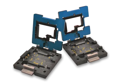
RTI's PCB module test sockets eliminate the need for complete test fixtures when validating complex electronic assemblies. These sockets are built to support multi-chip modules, SMT components, and flexible PCB layouts found in wireless communication modules, microcontroller boards, display modules, and other integrated assemblies.
Each socket enables simultaneous electrical contact to test points on both the top and bottom of the device under test. This approach is ideal for capturing performance data without relying on traditional test press fixtures. Like our custom IC sockets, every design is customized for your mechanical and electrical requirements, delivering precise alignment, signal integrity, and long-term reliability in both development and production test environments.

▪ Perfect Device Fit
Precisely align the UUT to spring pins using a combination of device characteristics such as tooling holes, castellated contacts, and more; ideal for UUTs with small test pads or tight pitches.
▪ Versatile Design
Each socket is built to the form and function of the unit under test. Typically used during In-circuit test, these sockets are mindful of UUT operational requirements.
▪ Rapid Prototyping
Rely on custom PCB module test sockets to perform early-stage testing of your modules in their final development before ramping up to production levels using larger fixturing.
▪ Comprehensive Solutions
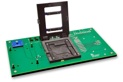
Pair your PCB module test socket with a mating adapter board that routes out signals to various connectors, header pins, plated through holes, and more.
PCB Module Test Sockets for Complex Devices
")
RTI's PCB module test sockets eliminate the need for complete test fixtures when validating complex electronic assemblies. These sockets are built to support multi-chip modules, SMT components, and flexible PCB layouts found in wireless communication modules, microcontroller boards, display modules, and other integrated assemblies.
Each socket enables simultaneous electrical contact to test points on both the top and bottom of the device under test. This approach is ideal for capturing performance data without relying on traditional test press fixtures. Like our custom IC sockets, every design is customized for your mechanical and electrical requirements, delivering precise alignment, signal integrity, and long-term reliability in both development and production test environments.
▪ Perfect Device Fit
Precisely align the UUT to spring pins using a combination of device characteristics such as tooling holes, castellated contacts, and more; ideal for UUTs with small test pads or tight pitches.
▪ Versatile Design
Each socket is built to the form and function of the unit under test. Typically used during In-circuit test, these sockets are mindful of UUT operational requirements.
▪ Rapid Prototyping
Rely on custom PCB module test sockets to perform early-stage testing of your modules in their final development before ramping up to production levels using larger fixturing.
▪ Comprehensive Solutions
Pair your PCB module test socket with a mating adapter board that routes out signals to various connectors, header pins, plated through holes, and more.
Product Details & More
Here, you'll find helpful links, PDF downloads for manuals and brochures, and related blog posts. For further assistance, please contact our customer support team.
Here, you'll find helpful links, PDF downloads for manuals and brochures, and related blog posts. For further assistance, please contact our customer support team.
Alternatives to Test Presses
These custom test sockets are typically used for functional or in-circuit testing of PCB-based module devices during the product development and characterization stage – before ramping up to panelized test or final test scenarios. Depending on the UUT's on-board components, test points, and alignment features, PCB module sockets may make more sense for your lab since they occupy less bench space, are a lower cost model, and can have a shorter lead time than larger format test fixtures.
Custom PCB module test sockets also provide closer working areas than their scaled up test press counterparts. Large openings in the socket's lid reveal exposed SMD components such as sensors, antennas, high speed connectors, and let you place your test tools within a few millimeters from the surface of the UUT.
Contact us to discuss your unit under test and see if a socket is the right fit for your needs.
Castellated Contact Options
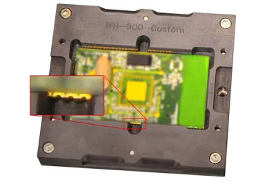
Devices with castellated contacts at the perimeter of the PCB can be probed using different methods, depending on the nature of the pads themselves.
For UUT modules not relying on castellated contacts for alignment purposes, one or more pointed tip spring pins can make contact with the small gold plated rectangular landing pads on the surface surrounding the castellation. In situations where pads are not present around the castellation, we utilize pins with a tip diameter larger than the cutout to both roughly align the UUT and ensure a secure electrical connection during test.
To explore all available alignment and contact options for your specific UUT and testing needs, we recommend submitting top/bottom layer STEP or GERBER files of your module to an RTI engineer for a thorough review.
Custom Component Clearances
For those tiny, yet critical surface mount components sitting close to your test points, we carefully mill out small pockets, ensuring no pressure or obstruction during loading. We tailor our socket bases and lids to apply both compression force and provide adequate backplane support to specific areas on the UUT while avoiding sensitive on-board SMT components. These cutouts not only ensure the UUT rests flat when loaded into the socket, they can also provide openings for improved airflow or access to specific areas on the UUT during test.
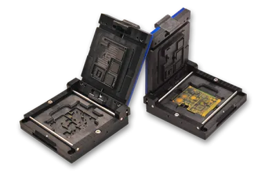
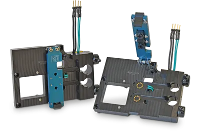
Dual Sided Probing
Our special interposer lids integrate PCB's and short length pogo pins that directly engage with the test points on the top side of your device. Within the lid, there's a cleverly designed mini-PCB that channels signals out from the UUT to a series of contacts that re-engage with the socket body.
Multiple interconnect configurations are available for routing signals between the lid and the test board under the socket. See our Interposer Lids infosheet which highlights the different methods. For those setups requiring contact on both sides of the device, we use a precise alignment method involving non-plated holes on the UUT. Additionally, to make sure everything lines up perfectly and stays put, keyed dowel pins in the lids serve as a guiding system for a snug fit to the socket body.
RTI's PCB Module Test Sockets Gallery
Click on an image to expand.


Already Have an RTI Socket?
Request a copy of your RTI socket drawing by submitting the form below. You must submit a drawing number or engraved socket number. Your Email domain must be associated with your company for consideration. If requesting drawings on behalf of another company, please provide contact information of someone within the socket-holder's company who can verify your affiliation and drawing request.
Request a copy of your RTI socket drawing by submitting the form below. You must submit a drawing number or engraved socket number. Your Email domain must be associated with your company for consideration. If requesting drawings on behalf of another company, please provide contact information of someone within the socket-holder's company who can verify your affiliation and drawing request.
Request Socket Drawing
Drawing Number Example

Engraved Socket Number Example
")


")
