Mechanical Press Fixture Kits
Lever-Actuated Bed-of-Nails Test Fixtures for Complex PCB and Module Testing
RTI's mechanical press fixture kits are engineered for PCB, hybrid module, and high pin count device-level testing, particularly when a standard test socket and breakout board cannot meet the application requirements. These lever-actuated, bed-of-nails fixtures provide a turn-key solution for both simple and complex assemblies, supporting dual-sided probing and integration of driver components required during test.
Compact, portable, and easy to operate, each mechanical test fixture kit is built for repeatability and efficiency in mid to high-volume environments.
▪ Effortless Operation
Lever-actuated test fixtures with 100% vertical compression provide consistent, reliable contact. Easy to use and gentle on sensitive devices.
▪ Precision Engineering
Each mechanical test fixture is built with stainless steel hardware and ball-bearing linear guides to ensure smooth operation and repeatable test results.
▪ Quick Changeover Capability
Interchangeable lids and device-specific modules enable fast product changeovers using the same test press base, improving throughput in lab and production use.
▪ Flexible Test Configuration
Featuring a universal press base and interchangeable bed-of-nails interface modules, these mechanical press fixture kits support a wide range of device sizes and test setups, making them ideal for both small- and large-scale applications.
Mechanical Press Fixture Kits
Lever-Actuated Bed-of-Nails Test Fixtures for Complex PCB and Module Testing
RTI's mechanical press fixture kits are engineered for PCB, hybrid module, and high pin count device-level testing, particularly when a standard test socket and breakout board cannot meet the application requirements. These lever-actuated, bed-of-nails fixtures provide a turn-key solution for both simple and complex assemblies, supporting dual-sided probing and integration of driver components required during test.
Compact, portable, and easy to operate, each mechanical test fixture kit is built for repeatability and efficiency in mid to high-volume environments.
▪ Effortless Operation
Lever-actuated test fixtures with 100% vertical compression provide consistent, reliable contact. Easy to use and gentle on sensitive devices.
▪ Precision Engineering
Each mechanical test fixture is built with stainless steel hardware and ball-bearing linear guides to ensure smooth operation and repeatable test results.
▪ Flexible Test Configuration
Featuring a universal press base and interchangeable bed-of-nails interface modules, these mechanical press fixture kits support a wide range of device sizes and test setups, making them ideal for both small- and large-scale applications.
▪ Quick Changeover Capability
Interchangeable lids and device-specific modules enable fast product changeovers using the same test press base, improving throughput in lab and production use.
Product Details & More
Here, you'll find helpful links, PDF downloads for manuals and brochures, and related blog posts. For further assistance, please contact our customer support team.
Here, you'll find helpful links, PDF downloads for manuals and brochures, and related blog posts. For further assistance, please contact our customer support team.
Mechanical Press Fixture Kits
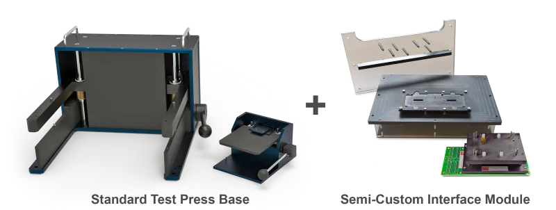
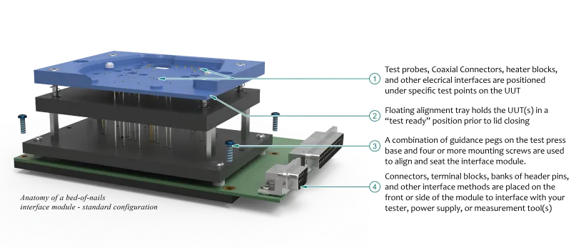
Our mechanical press fixture kits feature standardized 'universal' test press bases with customized, interchangeable, device-specific interface modules and lids. They offer large working areas with rough and fine alignment features for ease of use when loading and removing your unit(s) under test (UUT). Test press bases have a fixed cost per footprint while the device specific interface modules are priced according to the complexity of your UUT(s), routing configuration, and test requirements.
Devices Commonly Tested
- Bare and Populated PCBs, panels, and PCB Modules/Sub-assemblies
- Wearable and Implantable Medical Devices
- 5G, BLE, NFC, and other wireless TxRx devices
- Glass panel and touch sensors
- Gas, temperature, and pressure sensors
- Mechanically functioning electro-mechanical assemblies
- Final assemblies and products with unconventional footprints
Use & Test Applications
- Programming devices installed on a PCB module
- Mid-volume engineering test of individual or panel PCBs
- Functional Test of sub-assemblies with driver components
- Final Test of complete products
- RF Shielded and isolated test environments
- Temperature controlled environments
Common Design Options
- Single or Multiple test sites depending on UUT size
- Device pitches down to 0.6mm pitch centers
- High current, low force, and coaxial probes
- Multiple length probes for test points on different UUT planes
- Inclusion of driver components and test hardware
- Signal routing to connectors or test interface of choice
- Integrated heat sinks and heater blocks
- Test areas extend beyond the edges and below the base fixture
Contact us for a free quote or for more information.
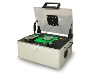
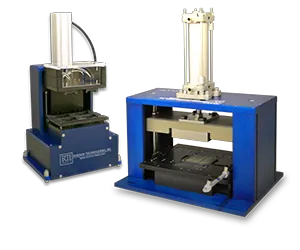
750 Series – Small Mechanical Press Fixture Kit

click to enlarge
RTI's 750 Series benchtop fixture kit is a compact tool combining ease of use, operator efficiency, and repeatability in engineering, production, and characterization environments. It's an ideal solution for testing small PCBs, modules, and electro-mechanical sub-assemblies considered too large or too complex for a custom test socket.
The 750 Series uses a built in vertical-clamshell compression lid that can be made universal with an array of drilled holes for user installation of stand off plates, or made dedicated to the UUT to apply force at specific areas across the device.
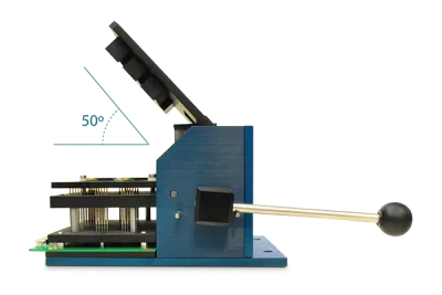
Open Position
The lid sits at a 50˚ angle when the press is in the open state, giving the operator ample room to load and unload UUT(s) between test. The height of the interface module and length of standoffs on the lid impact this working area.
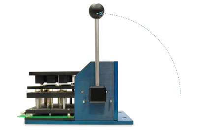
Resting Position
As the lever is pulled to close the lid, it first comes to rest in a horizontal position parallel to the baseplate. The standoffs installed on the lid sit above the UUT(s) without making contact and the UUT does not engage with the pogo pins.
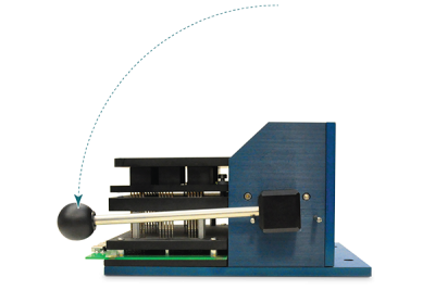
Closed Position
As the lever is fully engaged, the lid travels 0.34" vertically on linear bearings to bring the fixture into a closed "test" position. This vertical travel applies even compression force across the UUT as the pogo pins are engaged.
Additional Features and Benefits
- Common test area is 3.0" x 5.25" (can be extended)
- Base weight <15lbs
- Floating tray for precise alignment and easy loading of UUT
- Optional coaxial probes and/or switch probes
- Fine pitch test probes and coaxial probes available to 0.6mm
- Multiple test sites for A/B test or volume testing
- Open architecture for airflow across UUT(s)
- PCB used in Interface Module – no discrete wiring
- Pneumatic pistons to physically engage buttons, switches or other parts of the UUT
750 Series Examples
Click on an image to expand.


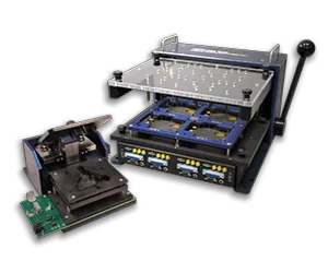
752 Series – Large Mechanical Press Fixture Kit

click to enlarge
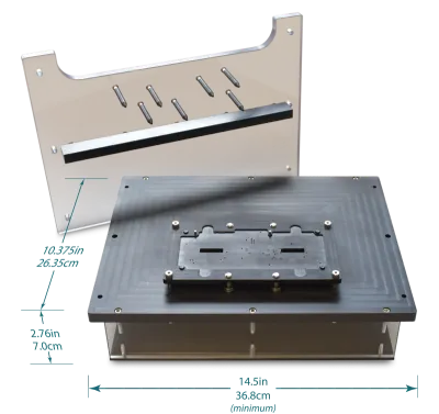
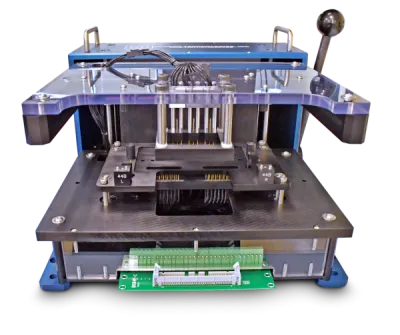
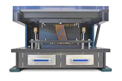
RTI's 752 Series is our most popular benchtop fixture kit combining ease of use, operator efficiency, and repeatability in prototyping, engineering, production, and characterization applications. It's available in multiple width footprints making it an ideal solution for in-circuit and functional testing of large scale and complex PCBs, MCMs, and other electro-mechanical sub-assemblies both before and after separation from a PCB panel.
The 752 Series uses a geared toggle clamp mechanism that gives significant mechanical advantage during use. The extended arms use linear bearings traveling on four stainless steel vertical guides to keep the lid in a horizontal position as the press is closed and the UUT is engaged.
See the "Interface Modules" section to learn more about the 752's UUT interface options.
Additional Features & Benefits
- Common test area is 8.0" x 13.0" (can be extended)
- Base weight <50lbs
- Optional risers for back-side cable exit
- Fine pitch test probes and coaxial probes available
- Multiple test sites for mid-volume batch testing
- Open architecture for airflow across UUT(s)
- PCB(s) to route signals, or hand wire wrapped pins (optional)
- Quickly and easily removable from the base press
- Integrated driver components required during test (optional)
752 Series Examples


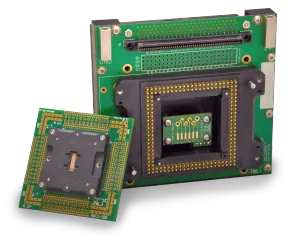
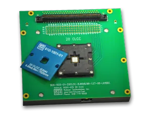
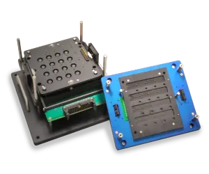
Interchangeable Modules: Quick Swap Interfaces for Fixture Kits
Explore the versatility of our interchangeable interface modules, designed to reliably probe test points positioned anywhere on your UUT(s). Our quick swap interface modules are crafted to perfectly align with your UUT footprint and specific usage requirements. Featuring a bed-of-nails style test bed, these modules provide precise routing of signals from your UUT to other sub-assemblies or directly to your chosen connectors to enhance your test setup's efficiency and accuracy.
All interface modules feature a floating tray system supported by linear bearings and coiled springs. This allows the UUT(s) to gently descend onto a bed-of-nails pogo pin array as the fixture reaches the testing position. This unique mechanism, coupled with the ability to swap out floating trays as UUT specifications evolve, eliminates the need for frequent module replacements.
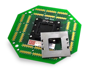
Interchangeable device-specific interface modules can be considered the heart of our fixture kits. They are responsible for:
- Fine alignment of UUT(s) to pins at device loading, providing electrical contact to the bottom, sides, and/or top of the UUT(s) during test,
- Integration of any customer supplied driver boards, displays, status LEDs, custom wiring, and any other components required by the UUT during test.
- Using a RTI designed routing PCB or providing ample space for hand wiring to route signals out to mating connector(s), header pins, plated thru holes, terminal blocks, or any other standard interface of choice.
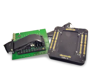
750 Series Interface Modules
752 Series Interface Modules
752 Series Lids Overview
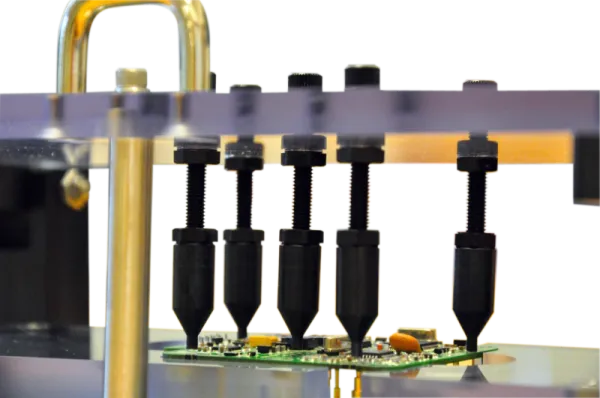
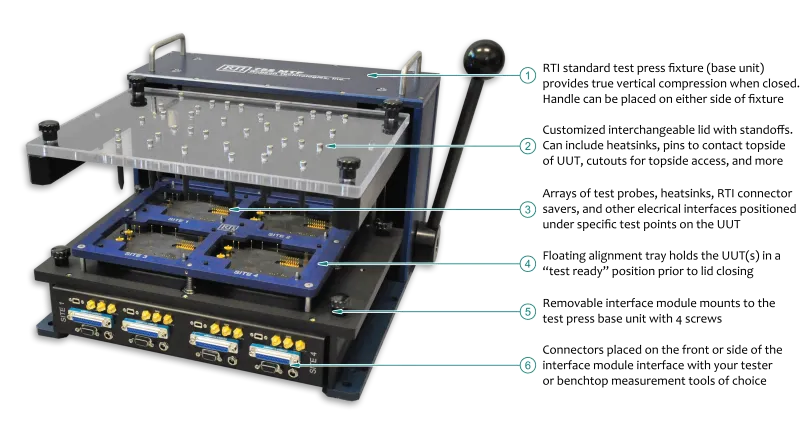
Like the interface module, lids are both device specific and easily removable from the test press base. Lids can include a variety of stand-off styles, from copper heatsinks and machined blocks to adjustable pegs positioned over key areas on the UUT(s) that apply compression force when in the test position. They can also be customized in a variety of ways to incorporate topside test points, provide UUT cooling, direct access to the UUT during test, and more.
RTI engineers the removable interface module and customizable lid to suit your UUT footprint and test specifications. This includes the bed-of-nails style pogo pin block to contact the bottom side of the UUT, the UUT alignment tray, and a PCB adapter board that routes signals to your test interface of choice. Contact us if you are interested in developing your own interface module for your 750 or 752 Series fixture base.
Interface Module Examples
Click on an image to expand.


Getting Started with RTI
A working solution starts with a working understanding
The following customer supplied information is required to ensure RTI meets an on-time schedule and provides an error-free test fixture solution. Incomplete data packages required at the time of design will cause project delays and significant changes to scope of work may result in an order that cannot be completed. RTI can provide a mutual NDA or fill out your company's mutual NDA if necessary, before exchanging any sensitive information.
Information required at time of quote:
An RTI Applications engineer will review each Statement of Work (SOW) and define any additional special features before submitting a quotation. The quote provides a detailed description of design and test requirements and includes essential information needed to satisfy these requirements.
- Minimum center to center spacing, pad size, and number of test points
- Alignment features available on the DUT
- Special test probes required
- Internal routing or wiring
- Intended interface with tester
- Type of fixture base platform and modifications
- Inclusion of sub-assemblies and other components
- Environmental and operational emulation requirements
The RTI Applications Engineer will request additional details about this essential information if not covered in your original SOW.
Information required at time of design:
RTI's mechanical and/or PCB design engineers will require technical drawings, sample(s) of the Unit(s) Under Test, and access to any other customer provided components that need to be included in the final product.
Files should include the top layer and/or silkscreen layer to identify installed components and relative positioning. Files should be combined and compressed in .zip format when possible and emailed to sale@electricaer.com. Contact us if the files are too large to send via email.
Accepted File Types:
- GERBER files that include top/bottom silkscreen and any layers of interest
- 3D STEP format
- CAD in .dwg or .dxf format
Additional Information and Samples:
- A sample device (assembled) might be needed at time of design.
- A sample device (non-functioning okay) will be needed at time of production for multi-point quality assurance prior to shipping.