How to Use an In Circuit Tester Effectively?

In the realm of electronic testing, the in circuit tester (ICT) stands as a critical tool for manufacturers. Its primary function is to help identify defects within assembled circuit boards swiftly and accurately. According to a recent report from the Electronic Testing Association, incorporating ICT can enhance fault detection rates by up to 90%. This significant improvement highlights the necessity of mastering its use.

Expert Alex Thompson, a leading figure in circuit board testing technology, emphasizes, “Efficient use of an in circuit tester is key for reducing production costs and minimizing errors.” His insights underscore that while ICTs provide substantial benefits, they can also present challenges if not used correctly. Operators often overlook certain settings or fail to adapt testing procedures to specific designs, leading to potential misdiagnoses.

The reality is that even with advanced technology, testing processes require careful consideration. It’s essential to continuously evaluate how an in circuit tester is applied. Regular training and updates on best practices can prevent common errors. In the fast-paced world of electronics manufacturing, striving for accurate testing practices is not just beneficial but essential for quality assurance.

How to Use an In Circuit Tester Effectively?

Understanding In Circuit Testers and Their Functions

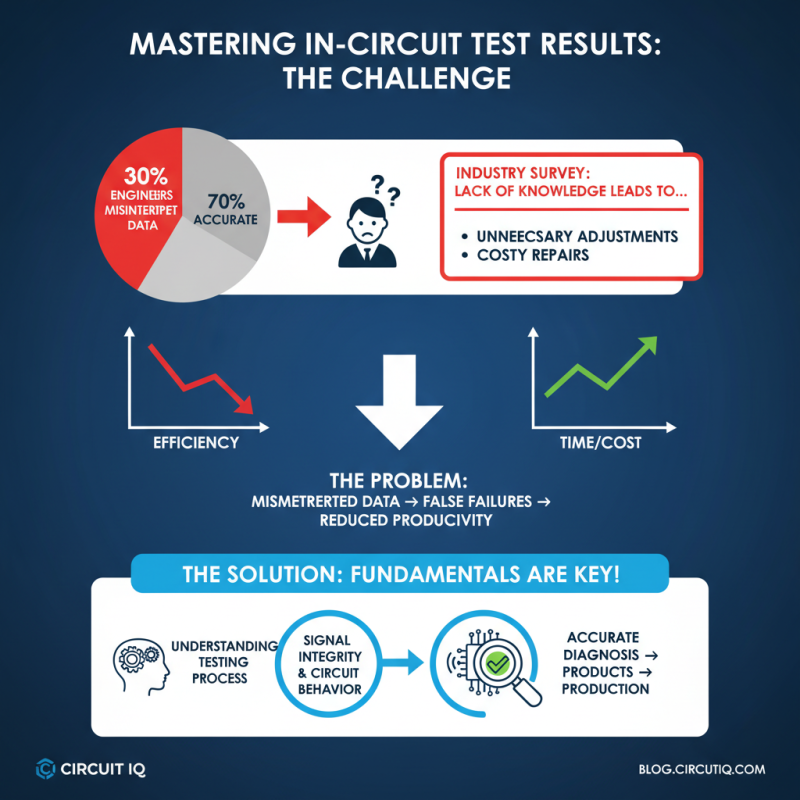
In-circuit testers (ICTs) play a crucial role in electronics manufacturing. They are used to validate the functional performance of printed circuit boards (PCBs). These testers can detect faults such as shorts and opens, ensuring quality control. Recent industry reports indicate that up to 20% of faults may go unnoticed without proper testing. This can lead to costly recalls and customer dissatisfaction.

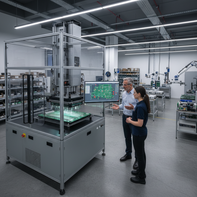
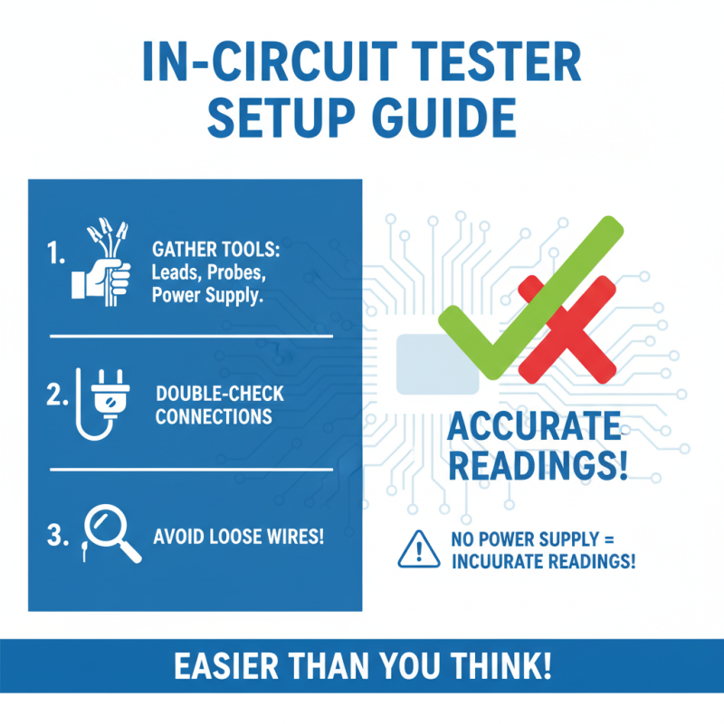
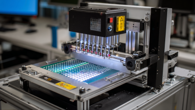
Understanding how ICTs operate is essential for effective use. They apply probes directly to the PCB to check electrical characteristics. This method allows for high accuracy and repeatability, with data suggesting a testing accuracy rate of over 95%. However, users must be aware of potential limitations. Incorrect programming or hardware setup may cause false positives. Attention to detail during the setup phase is crucial.

Many manufacturers overlook the importance of operator training. Skilled technicians can significantly enhance testing efficiency. Industry guidelines recommend regular training sessions for operators. A gap in knowledge can lead to misdiagnosis, which affects production quality. Time invested in training pays off, reducing errors and improving overall performance.

Essential Tools and Equipment for Effective Testing

Using an in-circuit tester requires specific tools to ensure effective results. For starters, a reliable multimeter is essential. It measures voltage, current, and resistance accurately. According to industry data, multimeters with a precision of 0.5% or better significantly enhance testing reliability. They allow technicians to troubleshoot more efficiently, making fault detection quicker.

A function generator is another crucial tool. It produces various waveforms for circuit testing. Studies show that using a function generator can improve the understanding of circuit behavior under different conditions. However, not all generators offer the same quality. Choosing one with a frequency range suitable for your needs is vital. Inadequate frequency response may lead to misleading results.

Lastly, consider using oscilloscope probes with high bandwidth. They help visualize signal integrity in real-time. Interestingly, many users ignore the limitations of probes. Using the wrong type can distort the signals. This oversight can lead to incorrect assumptions about circuit performance. Each tool plays a role in achieving accurate testing outcomes. Familiarity with their functionalities can greatly affect the time spent on troubleshooting.

Step-by-Step Guide to Setting Up an In Circuit Tester

How to Use an In Circuit Tester Effectively?

Setting up an in-circuit tester can seem daunting. Start by gathering all necessary tools. You will need test leads, probes, and a reliable power supply. Double-check your connections. Any loose wires can lead to inaccurate readings.

Next, connect the tester to the circuit board. Ensure the board is powered down while you make these connections. Pay attention to the polarity of the connections. A mistake here can damage components. After the setup, power on the board and initiate the testing process.

As you start testing, monitor the readings closely. Are they within expected ranges? If not, re-evaluate your connections. Additionally, documenting your findings can help track inconsistencies. Be prepared for troubleshooting. Sometimes, the circuit behaves unexpectedly. Adjustments may be necessary, and this can require patience. Don't be discouraged by minor setbacks; each is a learning opportunity.

Best Practices for Interpreting Test Results Accurately

How to Use an In Circuit Tester Effectively?

Interpreting test results from an in-circuit tester can be challenging. An industry survey showed that 30% of engineers misinterpret data due to a lack of knowledge. This often results in unnecessary adjustments or repairs. Understanding the testing process is essential. Focus on the fundamentals of signal integrity and circuit behavior.

Always cross-reference your data with previous measurements. A study found that 45% of discrepancies in test results occur when isolated readings are taken. Use consistent testing environments to minimize variables. Validate your findings against standard benchmarks. This practice can help reveal potential issues before they escalate.

Sometimes, overconfidence leads to oversight. Relying solely on the tester output without further analysis can be risky. Inspect physical components and trace connections regularly. This proactive approach improves accuracy and catches subtle defects early. Remember, data is only as good as the interpretation behind it. Enhancing your analysis skills will lead to better outcomes in circuit testing.

Common Troubleshooting Techniques During In Circuit Testing

In-circuit testing (ICT) is vital for identifying faults in electronic systems. Effective troubleshooting techniques enhance the accuracy of ICT. One common method is signal tracing. This involves following the signal path through the circuit. Various industry reports indicate that around 45% of errors can be isolated this way. Technicians can pinpoint issues quickly, reducing downtime.

Another technique is the use of a voltmeter to measure voltage levels at critical points. Many experts suggest that maintaining proper voltage levels can prevent component failures. According to a 2022 study, nearly 30% of circuit failures stem from incorrect voltage readings. Therefore, understanding reference voltages is crucial.

Visual inspections also play an essential role. Trained eyes can catch physical damage like burnt components or soldering issues. A staggering 25% of faults can be traced back to these visible defects. However, relying solely on visual checks can be misleading. Sometimes, internal issues are not visible. This gap highlights the need for a combined approach to troubleshooting in circuit testing. By integrating these techniques, technicians can enhance their efficiency and effectiveness.

Go to Top