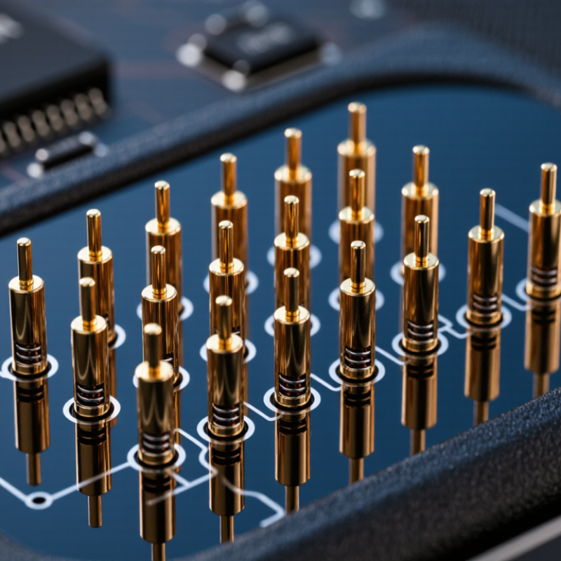
Micro pogo pins are compact, spring-loaded electrical contacts used where space, repeatability, and serviceability matter. They appear inside smartwatches, medical instruments, charging docks, test fixtures, and compact industrial devices. Unlike ordinary soldered joints, each pin uses a miniature plunger, spring, and conductive barrel. The spring maintains contact pressure while the plunger tolerates small alignment changes. A tiny detail, but a critical one.
Grand View Research estimated the global electrical connectors market at approximately USD 84 billion in 2023. Its report also projects continued growth through 2030, driven by electronics, vehicles, communications equipment, and automation. MarketsandMarkets identifies miniaturization and higher-density interconnects as important connector trends. These reports do not isolate micro pogo pins as a separate category. That limitation matters. Market figures should not be presented as direct micro pogo pin revenue.
As Mill-Max engineering guidance commonly emphasizes, “Contact reliability depends on maintaining stable pressure and controlled contact geometry.” This principle explains why plating, stroke length, spring force, and operating current require careful selection. A gold-plated contact may reduce oxidation, but it cannot correct poor tolerances or excessive contamination. Engineers often inspect contact marks under magnification after repeated compression testing. Real products are less perfect than catalog drawings.
This guide explains what micro pogo pins are, how their internal parts work, and why their performance changes under vibration, wear, shock, and environmental exposure. It also examines electrical resistance, current limits, mounting methods, and testing practices. The goal is practical understanding, not exaggerated precision. Small contacts deserve serious engineering.
Micro pogo pins are miniature, spring-loaded electrical contacts designed to transfer current or signals between two surfaces. Unlike a fixed metal contact, each pin has a moving plunger that compresses during connection. This movement helps maintain contact when surfaces are not perfectly aligned.
A typical micro pogo pin contains a conductive plunger, a cylindrical barrel, and a small spring. The barrel guides the plunger and supports the contact path. The spring creates continuous force against the mating surface. Many designs use protective plating to reduce oxidation and contact resistance. The term “micro” is not fully standardized, so dimensions vary by application. That detail matters.
Very small pins may have diameters below one millimeter. Their compact size supports dense circuit layouts and space-limited devices. Stroke length, spring force, current rating, and mechanical life must match the assembly. Too little force can cause unstable signals. Too much force may damage delicate contact pads. Engineers normally inspect these values through repeated compression tests, not appearance alone.
When two surfaces meet, the plunger moves into the barrel and the spring compresses. This stored force keeps the conductive surfaces touching during vibration or minor movement. Contact geometry also affects performance. A rounded tip may tolerate alignment errors, while a pointed tip can provide more concentrated contact pressure. In real assemblies, contamination and uneven mounting remain common concerns. The simple structure can be surprisingly sensitive.
Micro pogo pins are miniature spring-loaded connectors for compact electronics. A typical pin contains a plunger, barrel, spring, and plated contact surfaces. When the plunger meets a mating pad, the spring applies controlled force. This pressure breaks through light oxidation and maintains contact during small movements. The pin does not simply touch. It wipes.
That wiping action creates reliable electrical contact. Gold-plated surfaces usually reduce corrosion and stabilize contact resistance. Correct compression is critical. Too little force can cause intermittent signals. Too much force can deform pads or shorten service life. Engineers therefore match stroke, spring force, pitch, and current rating to the application. Micro sizes vary, but many designs use diameters below 2 millimeters. Very small parts leave little room for manufacturing error.
Market data shows why this engineering matters. MarketsandMarkets forecasts the global connector market will grow from about 84.3 billion dollars in 2023 to 114.7 billion dollars by 2028. Grand View Research also identifies miniaturized electronics as a major growth driver for advanced interconnects. These figures describe the wider connector industry, not micro pogo pins alone. Testing still matters more than forecasts. Designers should measure resistance after repeated compression, vibration, humidity, and contamination exposure. A clean laboratory result may not survive a pocket, a vehicle, or a wearable device. I would not call any contact perfectly reliable. Clearance, plating quality, alignment, and real operating conditions can quietly change the result.
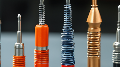
A micro pogo pin is a spring-loaded electrical contact for tight spaces. Its barrel provides the outer conductive path and protects internal parts. Inside, a miniature spring pushes the plunger toward a mating pad. This pressure helps maintain contact when the device experiences vibration, slight movement, or assembly variation. The plunger tip may be flat, pointed, or rounded. Each shape creates a different contact pattern and wear behavior.
The spring controls travel, contact force, and recovery after compression. Too little force can increase electrical resistance or cause intermittent signals. Excessive force may damage delicate pads or increase mechanical stress. The internal stop limits plunger movement and prevents over-compression. A rear terminal connects the pin to a circuit board, cable, or testing fixture. Insulating seals can reduce dust and moisture entry, although protection depends on the complete assembly.
Material selection matters. Conductive alloys support current flow, while surface plating helps resist oxidation and repeated wear. Engineers usually check contact resistance, spring force, working travel, and cycling performance. They also inspect the pin under magnification after testing. Tiny particles can change results. In practice, no design is perfect. A pin that performs well in a clean laboratory may behave differently after skin oils, dust, or thermal expansion appear. Therefore, real application testing remains essential, even when calculations look convincing.
Micro pogo pins are miniature spring-loaded electrical contacts for repeated, space-limited connections. A plunger compresses an internal spring against a barrel, preserving contact during vibration or slight misalignment. Their performance depends on spring force, contact stroke, surface plating, and assembly tolerance. Small details matter.
Wearable devices are a major application. The Worldwide Quarterly Wearable Device Tracker reported 520.5 million wearable devices shipped globally in 2023. A separate 2023 analysis by Grand View Research valued the wearable technology market at approximately 61.3 billion dollars in 2022. Smartwatches, health monitors, and smart glasses use micro pogo pins for charging cradles, removable sensors, and service access. These contacts can eliminate exposed charging sockets and support thinner housings. Medical equipment also uses them in compact monitors, sensor modules, and calibration fixtures. Engineers must verify contact resistance, cleaning methods, and sterilization compatibility.
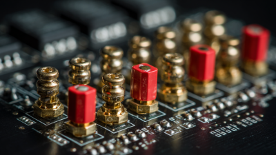
Consumer electronics use micro pogo pins for battery interfaces, camera modules, keyboards, and production test points. Factory fixtures often arrange dense pogo-pin arrays for fast circuit-board testing. Test engineers should check mating cycles, angled insertion, current loading, and environmental exposure. A connection that works in a clean laboratory may fail after sweat, dust, or repeated docking. This weakness is easy to underestimate. Designers sometimes prioritize minimum size and overlook debris buildup or spring fatigue. Micro pogo pins are practical, but their reliability depends heavily on the surrounding mechanical design.
Micro pogo pins are spring-loaded electrical contacts made from a plunger, barrel, and internal spring. When the plunger is compressed, spring force maintains contact between mating surfaces while allowing repeated connection and disconnection.
The chart shows representative contact-pitch ranges commonly considered for different compact applications. Actual values depend on current, voltage, mechanical tolerance, insulation, and required contact density; there is no single universal pitch for each application.
What Are Micro Pogo Pins and How Do They Work?
Micro pogo pins use a spring-loaded plunger, barrel, and internal spring to maintain electrical contact. When compressed, the plunger moves slightly and absorbs small assembly gaps. This mechanism supports reliable charging, testing, and signal connections in compact devices. Small does not mean simple.
Performance depends heavily on contact resistance, compression distance, spring force, plating, and alignment. Many engineering datasheets target contact resistance below 50 milliohms, but this value can increase after contamination or repeated cycling. IEC 60512 test methods help engineers evaluate resistance, mechanical operation, and environmental durability. Those tests are useful, yet laboratory results may not represent a dusty handheld device.
Durability also depends on stroke control. Excessive compression can deform the spring or accelerate plating wear. Insufficient compression may cause intermittent signals during vibration. A 2024 Grand View Research analysis projects the global connector market to grow at about 6.6% annually through 2030, increasing demand for smaller interconnects. That growth does not guarantee better reliability. Engineers should compare cycle ratings, current limits, temperature ranges, and salt-spray results under the actual operating profile. Gold plating usually improves corrosion resistance, but it cannot repair poor alignment. I have seen designs focus on pitch while ignoring side loading. That is an expensive blind spot.
| Performance Dimension | Typical Micro Pogo Pin Data | How It Works or Why It Matters | Factors Affecting Performance and Durability | Selection Guidance |
|---|---|---|---|---|
| Basic Operating Principle | Spring-loaded plunger, internal spring, barrel, and conductive contact surfaces | The plunger moves against a mating pad or contact and the internal spring maintains normal force. Electrical current flows through the plunger, spring or conductive path, and barrel. | Misalignment, contamination, insufficient compression, and excessive side loading can interrupt electrical continuity. | Choose a design with a guided plunger and sufficient working stroke for the expected mechanical tolerance. |
| Overall Diameter | 0.5–1.5 mm is common for micro designs | A smaller diameter allows a denser contact layout and helps reduce the size of the connector or test fixture. | Reduced diameter generally limits current capacity, mechanical strength, and available spring volume. | Use the smallest diameter that still meets current, force, alignment, and mechanical life requirements. |
| Installed Height | 1.5–5.0 mm, depending on construction and stroke | Installed height determines the available package space and affects the amount of compression available after assembly. | Low-profile versions may have shorter travel and lower current or force ratings. | Verify the compressed and uncompressed heights against the housing, PCB, battery, or mating interface. |
| Working Stroke | 0.3–1.5 mm typical; application-specific designs may differ | The working stroke is the usable plunger movement over which the pin provides reliable contact force. | Operating near the end of the stroke can increase spring stress, wear, and contact resistance. | Allow enough stroke to absorb tolerance variation, but avoid bottoming out the plunger during normal operation. |
| Initial Contact Force | 20–150 gf at or near the specified initial position | Initial force is the spring force available when the plunger first touches the mating surface. | Force depends on spring rate, wire diameter, free length, plunger position, and material properties. | Use the lowest force that provides stable contact, especially for delicate pads, flex circuits, and small batteries. |
| Working Contact Force | 40–200 gf at the specified working stroke | Higher working force can improve resistance to vibration and surface films by maintaining stronger mechanical contact. | Excessive force can deform pads, increase insertion loads, accelerate wear, and reduce service life. | Define force at a specific compression distance; force values without a stroke position are difficult to compare. |
| Spring Rate | Approximately 0.05–0.30 N/mm for many small designs | Spring rate describes how much the force increases as the plunger is compressed farther. | A high spring rate produces greater force variation over tolerance changes and can increase mechanical loading. | Match the spring rate to the available compression, required contact force, and maximum allowable mating load. |
| Continuous Current Rating | 0.5–3 A for many micro pins; higher values require larger or specialized designs | Current capacity is limited by the conductive cross-section, contact resistance, temperature rise, and heat dissipation. | High current, small size, poor ventilation, and elevated ambient temperature can cause overheating and plating degradation. | Use the rating at the actual duty cycle and temperature. Consider multiple pins in parallel for higher current paths. |
| Signal Frequency Capability | Suitable for power, control, and low-to-moderate-speed signals; high-speed performance is application-specific | A pogo pin carries signals through a movable mechanical interface rather than a fixed soldered joint. | Parasitic inductance, capacitance, pin length, contact geometry, and return-path layout affect signal integrity. | For high-speed signals, evaluate impedance, insertion loss, crosstalk, grounding, and the complete connector structure. |
| Contact Resistance | Often below 50 mΩ when new and properly compressed | Low resistance reduces voltage drop and heat generation at the contact interface. | Oxidation, contamination, low contact force, surface roughness, vibration, and wear can increase resistance. | Specify the test current, compression position, mating surface, and environmental condition when comparing values. |
| Contact Material and Plating | Conductive copper alloys with nickel barrier layers and gold or other wear-resistant contact plating | The base alloy supplies mechanical and electrical properties, while plating helps control corrosion and contact resistance. | Plating thickness, hardness, porosity, mating material, and wiping action affect wear and long-term stability. | Select plating for the environment, current level, mating surface, expected cycles, and required corrosion resistance. |
| Mechanical Life | 10,000–100,000 cycles is common under controlled conditions | Mechanical life is the number of compression and release cycles before force, resistance, or movement falls outside specification. | Side loading, over-compression, abrasive contamination, high current, and poor alignment reduce life. | Use application-specific cycle testing because published life depends strongly on stroke, speed, load, and environment. |
| Operating Temperature | Approximately −40°C to +85°C for many general-purpose designs | Temperature changes affect spring force, material expansion, electrical resistance, and lubricant behavior. | High temperature accelerates oxidation and material aging; low temperature can increase stiffness and reduce lubricant performance. | Confirm the complete temperature range, including current-induced heating and storage conditions. |
| Environmental Protection | Open designs require a clean, dry environment; sealed assemblies can provide higher protection | The moving plunger creates a path where dust, moisture, oils, or salts may reach the contact area. | Humidity, salt spray, dust, corrosive gases, and liquid ingress can increase resistance and cause corrosion. | Use a sealed structure or protective housing when the application involves moisture, dust, sweat, or chemical exposure. |
| Alignment Tolerance | Typically limited; exact allowable offset depends on plunger tip and housing design | The plunger must remain within its guided travel while maintaining adequate overlap with the mating pad. | Angular misalignment and lateral force can cause binding, uneven wear, or damage to the mating surface. | Add alignment features, use a suitable tip shape, and keep lateral loads separate from the spring axis. |
| Mating Surface Requirement | Flat, clean, conductive pad with suitable hardness and finish | The tip needs sufficient surface contact to carry current while allowing a small wiping action to remove films. | Roughness, soft coatings, solder residue, oxidation, and pad deformation can produce unstable resistance. | Define pad size, finish, hardness, flatness, and allowable wear together with the pogo pin specification. |
| Common Tip Styles | Rounded, flat, pointed, crown, and multi-point contact tips | Tip geometry controls contact concentration, self-centering behavior, wiping action, and compatibility with the mating pad. | Pointed tips may mark soft surfaces; flat tips provide broad contact; crown tips can improve multi-point electrical contact. | Choose the tip according to pad material, available area, required wiping action, and acceptable surface marking. |
| Mounting Method | Press-fit, soldered, spring-contact module, or integrated connector assembly | The mounting method determines mechanical retention, electrical path length, assembly cost, and serviceability. | Poor retention, solder-joint stress, excessive insertion force, and thermal processing can affect reliability. | Select the mounting method based on production volume, rework needs, board thickness, and mechanical shock requirements. |
| Main Advantages | Compact size, repeatable spring force, detachable connection, and tolerance compensation | Micro pogo pins provide temporary or semi-permanent electrical connections without requiring a permanent soldered mating interface. | Performance still depends on cleanliness, alignment, compression, and correct current management. | They are well suited to compact electronics, battery contacts, charging interfaces, test fixtures, and removable modules. |
| Main Limitations | Limited current, sensitivity to contamination, wear of moving parts, and alignment requirements | The spring-loaded mechanism introduces mechanical complexity compared with a fixed soldered or welded connection. | Repeated cycling, vibration, high current, harsh chemicals, and excessive compression can shorten service life. | Consider a fixed interconnect when the connection is permanent, highly sealed, or exposed to extreme mechanical and environmental stress. |
| Recommended Verification Tests | Contact resistance, force-displacement, cycle life, current-temperature rise, vibration, humidity, and corrosion tests | Testing confirms performance under the actual compression, current, environment, and mating materials used in the product. | Testing only a new, clean component may not reveal degradation caused by wear, contamination, or environmental exposure. | Create acceptance limits for resistance, force, travel, temperature rise, visual wear, and continuity interruptions. |