
10 Best IC Test Socket Suppliers for Global Buyers?
Choosing an ic test socket supplier is not a simple price comparison. It is a decision about yield, repeatability, delivery risk, and long-term engineering support. In a production line, a socket may face thousands of insertions, thermal cycling, and tiny alignment errors. One worn contact can create false failures, wasted devices, and uncomfortable questions from management.
As semiconductor test consultant John O’Donnell puts it, “The socket is the test path, not merely the holder.” This perspective matters when comparing global suppliers. A capable manufacturer should explain contact technology, insertion life, signal integrity, temperature limits, cleaning methods, and package compatibility. It should also provide inspection records, sample data, and a realistic replacement plan. Attractive brochures are not enough.
Details reveal experience. Ask whether the supplier has supported QFN, BGA, LGA, wafer-level, or high-power packages similar to yours. Request measured contact resistance, mechanical drawings, tolerance data, and test results under actual operating conditions. Check response times across time zones. Confirm whether engineering changes are documented and traceable. Small things matter.
No ranking is perfect. Buyer priorities differ. A laboratory may value flexibility, while a high-volume factory may need stable cycle life and local inventory. I may be overly cautious, yet ignoring after-sales support often becomes expensive later. The following guide reviews ten ic test socket suppliers through practical criteria, including technical capability, quality evidence, customization, global service, and total ownership cost.
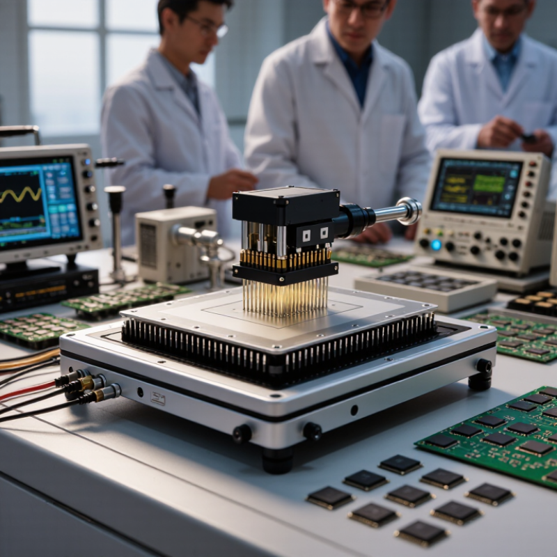
IC Test Sockets Explained: Types, Functions, and JEDEC Package Standards
IC test sockets connect a packaged integrated circuit to test equipment without permanently soldering the device. They support electrical testing, programming, burn-in, and failure analysis. In production validation, I have seen a small contact mismatch create unstable readings. The socket was not the only suspect.
Common types include open-top sockets, clamshell sockets, load-board sockets, burn-in sockets, and high-frequency sockets. Open-top designs suit frequent device changes. Clamshell models provide controlled pressure during repeated testing. Burn-in versions handle elevated temperature and extended operation. High-frequency sockets require short signal paths and carefully controlled impedance. Contact force, pin count, insertion cycles, and thermal expansion all affect performance.
JEDEC package standards help engineers match socket geometry with device packages. Standards cover outlines such as QFN, QFP, BGA, LGA, and fine-pitch variations. They define dimensions, terminal locations, and mechanical references, but they do not guarantee identical socket results. Check package tolerance, coplanarity, lid clearance, and board alignment. A supplier should provide drawings, material data, test evidence, and replacement contacts. Ask about actual cycle-life results, not only catalog claims. Small details matter. I once focused too heavily on package compatibility and underestimated cleaning needs. That mistake changed our inspection routine. Supplier reliability also depends on communication, sampling speed, and technical support across regions. The best choice is not always the cheapest socket.
| # | IC Package Family | Representative JEDEC Reference | Common Nominal Pitch | Typical Socket Configuration | Common Contact Technology | Primary Test Use | Key Buyer Evaluation Criteria |
|---|---|---|---|---|---|---|---|
| 1 | PDIP / DIP | JEDEC MS-001; verify the exact body and pin-count outline | 2.54 mm | Open-top ZIF or lever-actuated socket | Stamped or machined spring contacts | Prototype validation, through-hole devices, education, and low-volume production testing | Pin-count range, insertion force, contact resistance, mechanical durability, and compatibility with automatic test equipment |
| 2 | SOIC / SOP | JEDEC MS-012 or the applicable JESD95 package outline | 1.27 mm | Open-top ZIF or clamshell socket | Stamped spring contacts or pogo pins | Functional test, programming, burn-in, and board-level engineering verification | Lead coplanarity tolerance, socket alignment, contact life, package height, and cleaning access |
| 3 | PLCC | JEDEC MS-018; confirm the specific PLCC outline and pin count | 1.27 mm | Clamshell, extraction-lid, or ZIF socket | Spring-beam or stamped contacts | Firmware programming, device characterization, and legacy-system maintenance | J-lead retention, extraction clearance, latch reliability, contact wear, and package orientation |
| 4 | SSOP | Applicable JESD95 MO-series outline; confirm body width and lead count | 0.65 mm or 0.635 mm | Precision open-top or clamshell socket | Fine-pitch stamped contacts or pogo pins | Low- to medium-volume production test and engineering characterization | Lead alignment, coplanarity tolerance, insertion accuracy, contact pitch control, and socket replacement cost |
| 5 | TSSOP | JEDEC MO-153 is commonly referenced; verify the exact revision and dimensions | 0.65 mm or 0.50 mm | Fine-pitch ZIF, clamshell, or handler-compatible socket | Fine-pitch spring contacts or elastomeric contacts | Mixed-signal IC testing, programming, parametric test, and reliability screening | Lead-tip geometry, contact alignment, maximum insertion cycles, thermal range, and signal integrity |
| 6 | QFP / LQFP | JEDEC MS-026 and applicable JESD95 MO-series outline | 0.80 mm, 0.65 mm, or 0.50 mm | Clamshell, ZIF, or handler-compatible socket | Pogo pins, spring beams, or elastomeric interposers | Microcontroller, processor, automotive, and high-pin-count device testing | Lead coplanarity, corner protection, package warpage, thermal expansion, signal integrity, and handler interface |
| 7 | QFN / DFN | JEDEC MO-220 and related JESD95 outline families | 0.50 mm, 0.40 mm, or 0.35 mm | Precision clamshell or compression socket | Fine-pitch pogo pins, spring contacts, or elastomeric contacts | RF, power-management, sensor, and compact mixed-signal IC testing | Bottom-pad access, package seating, coplanarity, exposed-pad contact, inductance, and thermal performance |
| 8 | LGA | Package-specific JESD95 MO-series outline; verify the exact land pattern | 0.50 mm, 0.40 mm, or 0.35 mm | Compression, pressure-lid, or high-density test socket | Vertical pogo pins, spring probes, or elastomeric interposers | Processors, sensors, networking devices, and high-density system-in-package testing | Land coplanarity, compression force, probe planarity, high-frequency performance, and package warpage |
| 9 | BGA | JEDEC MS-034 and applicable JESD95 BGA outline | 1.00 mm, 0.80 mm, or 0.50 mm | Compression socket with a lid, stiffener, or load plate | Pogo pins, vertical spring probes, or elastomeric arrays | Processors, memory devices, FPGAs, and high-pin-count production test | Ball-grid alignment, compression force, coplanarity, thermal interface, power integrity, and socket life |
| 10 | FBGA / Fine-Pitch BGA | JEDEC MO-211, MO-216, or another applicable JESD95 outline | 0.80 mm, 0.65 mm, or 0.50 mm | High-precision compression socket or handler-compatible socket | Fine-pitch pogo pins, spring probes, or elastomeric interposers | Memory, application processors, AI devices, and high-speed digital characterization | Fine-pitch alignment, insertion repeatability, high-speed signal loss, thermal cycling, cleaning, and replacement lead time |
Note: JEDEC outline references identify package dimensions and land or lead geometry; they do not define one universal socket design. Buyers should confirm the exact package drawing, pin or ball count, body dimensions, temperature range, electrical bandwidth, test-handler interface, and required insertion-cycle rating before purchase.
Related Posts
-
How to Choose the Best Semiconductor Test Socket for Your Needs?
-
Understanding the Essential Role of IC Test Sockets in Modern Electronics Testing
-

Top Trends in Semiconductor Test Sockets for 2025 You Need to Know
-

Tailored Solutions for Optimizing Your In Circuit Tester Performance
-
Best Semiconductor Curve Tracer Tools for Accurate Measurements?
-
Exploring Market Trends for Air Presses at the 138th China Export and Import Fair 2025